ARTICLES

Is the following callout even valid? Since flatness is a form-only control, aren’t modifiers (MMC, LMC) not applicable? If it is a valid callout, why would it be used and how would you evaluate/measure it?
The reality is, to determine whether it is a valid callout, we need more information. Specifically, we need to know what type of feature it is being applied to. If this were applied to a single planar surface, then no, it would not be a valid callout due to the MMC modifier.
Here’s an expanded view of the callout to add some necessary clarity…
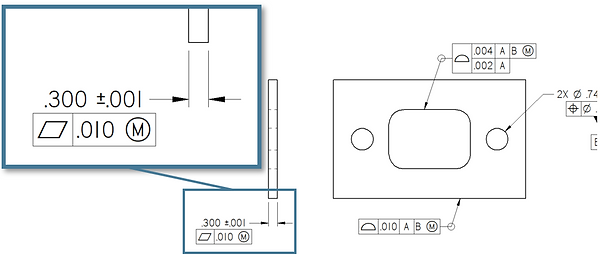
In this case, because the flatness is being applied to a Feature of Size (a width), it is indeed a valid callout based on ASME Y14.5-2009 (para. 5.4.2.1). The flatness tolerance in this case is controlling the form of the derived median plane. This same concept can also be applied to a cylindrical feature of size with a straightness callout.
So, if the callout is valid, then we need to address the two questions at the beginning of this post, namely why and how.
Why Would It Be Used?
Simply stated, this callout can be used when the local size (thickness) needs to be controlled more tightly than the overall form. Possibly plates that will be stacked or shims which will be flattened when assembled, etc.
Though often overlooked, a size tolerance also controls form (per Rule #1). In our example, the size tolerance would require that the entirety of the feature fit within two parallel planes that are .301” apart. But, when the flatness at MMC is added to the size tolerance, it removes the Rule #1 requirement. Which means that the only thing the size tolerance is controlling is the “local” size (localized thickness). The flatness callout then is controlling the overall form of the width (bow, etc). This also results in a Virtual Condition Boundary that cannot be violated based the accumulation of size and form variation. In our example, the virtual condition boundary would be .311” (MMC + Geometric Tolerance). So, there is a functional purpose for this callout. As an example, it may be acceptable that the part is bowed as shown below as long as the localized thickness is controlled more tightly –

How Would You Measure It?
How do you determine whether a part meets this design requirement? I’m going to try to be at least somewhat granular in answering. After all, if we cannot properly evaluate the callout, what purpose does the callout serve? There are two main methods used in industry to evaluate GD&T, functional gaging and CMM measurement.
Functional Gaging
With regard to functional gaging, we would need two gages. One would be a gage to check the local thickness such as opposing indicators. The part would need to be swept through the gage to ensure that the full extent of the feature stays withing the size tolerance.

The second would be a simple gage that has two parallel planes spaced apart .311” (Virtual Condition Boundary).

If the local size is within tolerance and the part passes through the virtual condition gage, it is a conforming part. It’s recommended to follow gaging principles laid out in Y14.43.
CMM Measurement
With regard to CMM measurement, how you evaluate GD&T may vary depending on the capabilities of the particular software. Some software will do much of the work automatically to evaluate GD&T. However, with the specific example we are considering (flatness at MMC applied to a width), it is very unlikely that the software will allow or correctly evaluate this callout automatically.
To verify the size requirements on a CMM, the part would need to be setup so as to allowing probing on both sides. You would need to take a series of opposing points throughout the extent of the feature, keeping in mind adequate point densities and proper point compensation methods. Each point to point thickness would need to be within the size limits.

For the flatness callout, you will need to construct a mid-point from each of the opposing point sets. Then, all of the midpoints would be used to construct a plane. Then you would add a flatness dimension to the constructed (median) plane. To calculate the total allowable flatness tolerance, you would need to look at the largest local size result. As an example, if the largest local size measurement was .300”, my flatness tolerance would be .011”. If the flatness result of the constructed median plane was less than .011”, then it’s a conforming part.

Depending on the software, you may be able to create a formula with a variable to calculate the flatness tolerance automatically. If all thickness measurements are within the size limits and the flatness of the median plane is within the allowable flatness tolerance, it is a conforming part. Much more could be said about measurement methods (and measurement uncertainty, etc), but hopefully this gives enough guidance to show how it can be measured.
Final Thought for Designers…
One last thought for designers that may need to control a feature of size in a similar manner. There is another method that will control the feature in a similar (though not identical) way that may be less costly for inspection (see graphic below). I offer this to make the point that there is often more than one way to control the desired functionality of a part, but they don’t all have the same cost-factor for manufacturing/quality. The more a designer understands current manufacturing/inspection methods and capabilities, the more cost-effective the design can be (while still clearly controlling the function of the part, which is the primary goal of GD&T). The main difference with this example is that the flatness is not linked to the feature of size and therefore can't leverage potential bonus tolerance.

Whether you are in design, manufacturing or quality, for GD&T to be implemented successfully, it's important for us to understand the what, why and how.
Importance of GD&T for Design, Manufacturing, and Quality
___________________________________________________
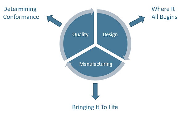
Whether your company is a part of the design process or manufacturing or quality, GD&T competency is critical for success. Regardless of what part of the process you are in, Applied GD&T can help you move forward with a successful implementation of Geometric Dimensioning & Tolerancing.
If you are in design, it's critical that you have a deep enough understanding to properly apply datums and tolerances that reflect the function of the part (while also considering current manufacturing and inspection capabilities). If you are a supplier in manufacturing or quality, I would argue that there is an even greater need to have a broad understanding of GD&T. Read on for more...
Design
If you control the design process, you need to have the knowledge of GD&T to apply datums and tolerancing that accurately reflect the function of the part. A lack of competence in design often leads to tolerancing that does not reflect the function of the part. This may lead to accepting bad parts and rejecting good parts. Also, when a designer/design team lacks an adequate competency in GD&T, oftentimes tolerances are needlessly tightened hoping that it will increase the likelihood of getting functional parts. In both scenarios, cost implications are obvious (and not-so-obvious).
When the GD&T does not correctly convey the function of the part, it cannot be manufactured and inspected with the assurance that conformance to the design equals a functional part. It may be an obvious statement, but for these reasons, it is critical that designers have a good working knowledge of GD&T and how to apply it optimally.
Manufacturing
Those in manufacturing need to make parts that conform to the GD&T (at competitive prices and turn-around time). Not understanding GD&T hinders you from being competitive and leads to less profit and more scrap. Properly understanding GD&T will enable you to estimate more accurately, and to establish a manufacturing process that is optimal from the start and that will minimize rejected parts. Again, as with design, there are obvious cost implications to poor GD&T competency in manufacturing.
Quality
For the full implementation of GD&T to be successful, we need to determine whether a part actually conforms to the design drawing. That's where quality/inspection comes in. If those in quality/inspection don't understand GD&T (and the proper techniques for evaluating GD&T), the implementation will obviously fail. Understanding how datums constrain degrees of freedom, how features of size are calculated, the rule of simultaneity, and how to report the results clearly are critical concepts for those in dimensional inspection. As with poor design, poor inspection will likely result in rejecting good parts and accepting bad parts.
Suppliers
The reality is that there are various "philosophies" of GD&T that are applied in different organizations and industries. Therefore, as a manufacturing or quality supplier, it's critical to have competency in the full breadth of the GD&T standard and how your customer may be applying it. It's also important to be know the difference between invalid GD&T and non-optimal GD&T. Both are issues but need to be handled differently. In light of that, it is critical to be able to intelligently communicate with the customer when there are legitimate issues with the GD&T on the print. It's never a fun scenario when you go to confront your customer about their crazy GD&T only to find out that the problem is actually a lack of understanding on your part. I know I've been there;)
Good Training (and lots of it) is Key
Whether your starting from scratch or looking to fill in some gaps in your GD&T competency, Applied GD&T is here to come alongside you to help you and your team move forward. Contact for more information.
CMM Programming with GD&T
___________________________________________________

There is a lot of experience, skills, and knowledge needed for a good CMM programmer. Indeed, as many manufacturing companies would attest, a good CMM programmer is hard to find. And when inspection equipment is seen as pure overhead, many companies have a difficult time paying a high salary for the level of skilled personnel needed to program their CMM's (after all CMM's aren't cutting chips!).
One skillset that is critical for CMM programming is an in-depth knowledge of Geometric Dimensioning and Tolerancing (GD&T).
It may seem obvious that a CMM programmer needs to understand GD&T but the depth of GD&T expertise necessary may not be realized. In reality, a good CMM programmer needs to understand GD&T just as well as a designer. A designer needs to know enough about GD&T to apply datums and tolerances that ideally reflect the function of the part following the applicable standard (ANSI or ISO). The CMM programmer needs to interpret the GD&T and then apply measurement strategies to correctly evaluate the part's conformance. If the CMM programmer doesn't understand the rules of GD&T as well as the designer, the implementation of GD&T will logically fail.
A significant challenge arises due to the varied "styles" of GD&T that is used on different prints. The CMM programmer needs to not only understand the GD&T standards (e.g. ASME Y14.5-2009) but also how it is applied by designers with varying GD&T "philosophies". Frequently GD&T is applied poorly or simply in an invalid way, but the programmer still needs to inspect the part and provide accurate results. This means that the CMM programmer needs to get "into the mind" of the designer by evaluating the print and observing how the designer uses datums and different geometric tolerances. And it may be necessary to interpolate the gaps or make the best judgment on what to do with an invalid or poor callout.
In many cases, the only way to properly work through poor/invalid GD&T callouts is to get clarification from the designer. But, oftentimes that is simply not an option. So, CMM programmers need to make the best decisions possible and their level of GD&T knowledge and experience makes a huge difference. And of course, they also should clearly document the methods used especially when the GD&T is not clear or invalid. The often-unspoken reality is that, depending on things like datum alignments and feature calculations, there can be significantly varied results on any given part.
The last thing anyone wants is a CMM that simply produces numbers. Once a CMM gets a reputation for being a random-number-generator, it can be hard to restore its place of value for manufacturing.
Making decisions for CMM programming with GD&T can be quite difficult. The more the CMM programmer understands GD&T and how it is applied in industry, the more likely they will be able to create a CMM program that properly determines part conformance. It's also important that the CMM programmer can provide results that give clear feedback to those in manufacturing to monitor and improve processes. The numbers that manufacturing needs for process feedback may be quite different than those that determine part conformance. If implemented well, CMM's can provide manufacturing significant value.
GD&T expertise is just one of the critical components for good CMM programming, if you have a CMM with PC-DMIS and you need some programming help, let me know. Whether it's bringing your PC-DMIS programmers up to speed or outsourcing your PC-DMIS programming, Applied GD&T is here to help.
For more information on GD&T training or CMM programming, just contact Applied GD&T.